About the project
Industrial IoT Terminal for monitoring/ control based on decisions taken in the cloud
Items used in this project
Hardware components
ARDUINO KIT BREADBOARD W/ WIRESSoftware apps and online services
Atmel Studio 7.0Hand tools and fabrication machines
Soldering IronStory
The argument that I have decided to use when i applied to this contest was "Industrial IoT Terminal for monitoring/ control based on decisions taken in the cloud". And to keep loyal to my idea I will elaborate a project that will show all the capabilities (or at least the most important) of the AVR IoT WG development board.
While I was thinking what to do as a project I'd been testing the development board finding out that the temperature sensor works good but, in some conditions, the temperature sensor included in the board could be influenced by the heat generated by rest of components (mainly the WifFi) in the board. Also to measure the temperature in hard environments (very hot or very humid) could be harmful for our development board.
Once started gathering all the electronics components that I used for another projects,I decided to use for this project the next main hardware to enhance the capabilities of the AVR IoT WG developent board:
- AVR IoT WG development board
- 2 Relays board.
- 1 DHT11 humidity and temperature sensor.
- I2C 16x2 Liquid Cristal Display
- 1 500mA LiPo battery
Having this hardware related with environment measurements I have decided to make a environment controller device, an incubator!
There is not a new stuff, you can find it everywhere, specially in industrial environments, such a farms, laboratories or hospitals, but we have got a great opportunity to make it IoT!
You can see the general connection diagram below.
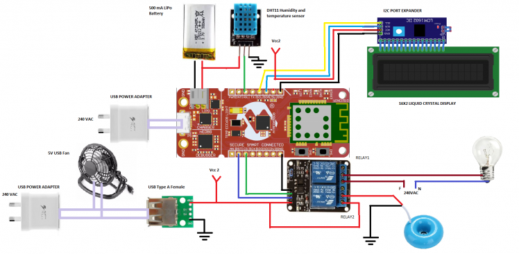
As you can see in the diagram above one 5V power supply will feed a permanent 5V USB fan, the humidifier and the relays . That's because we want to isolate the AVR IoT development board from the relays in order to avoid noise because of the switching. Also to make the board could run under batery we need to reduce power consumption.
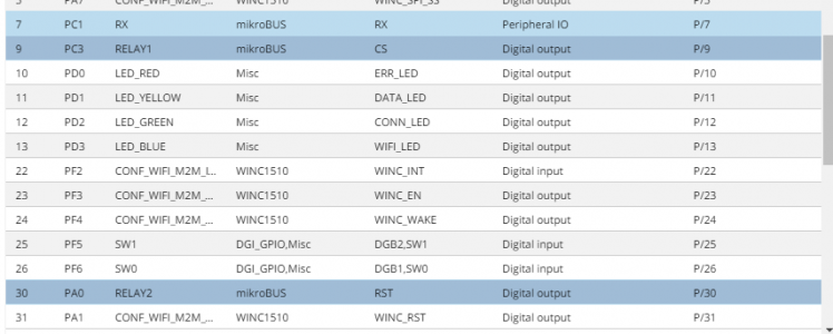
Relay 1 will be connected to CS ping in the board, Relay 2 to the RST pin and the DHT11 sensor to the RX pin.
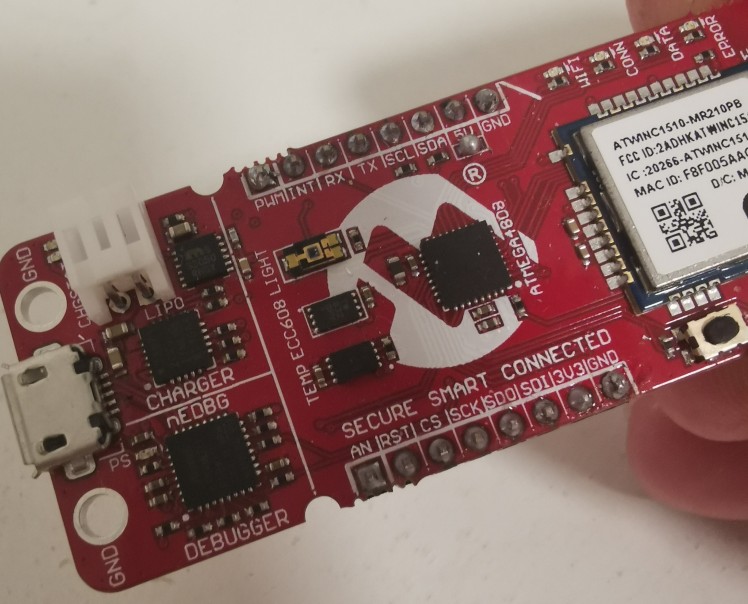
In order to make all this connections I will use a bread board and to connect the AVR IoT WG development board to the breadboard I've soldered male pin headers to the mikroBUS socket. It looks like that. Please note also that there is a short soldered in the R204 resistor, this is made to bring to the breadboard 5 Volts from the AVR IoT WG development board.
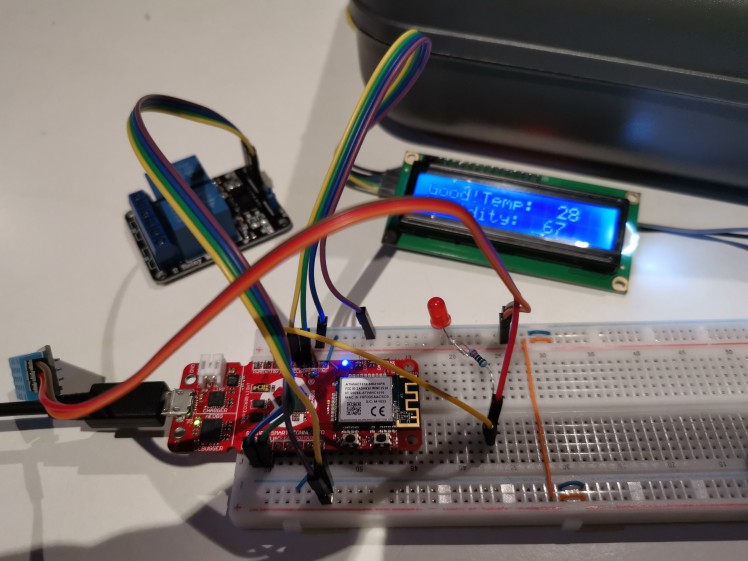
In order to start doing the AVR IoT WG development board programming and tests I've connected just the basic stuff, the LCD, the DHT11 humidity and temperature sensor and the relays, (on the last stage I will mount the rest stuff in the incubator box) see the image below.
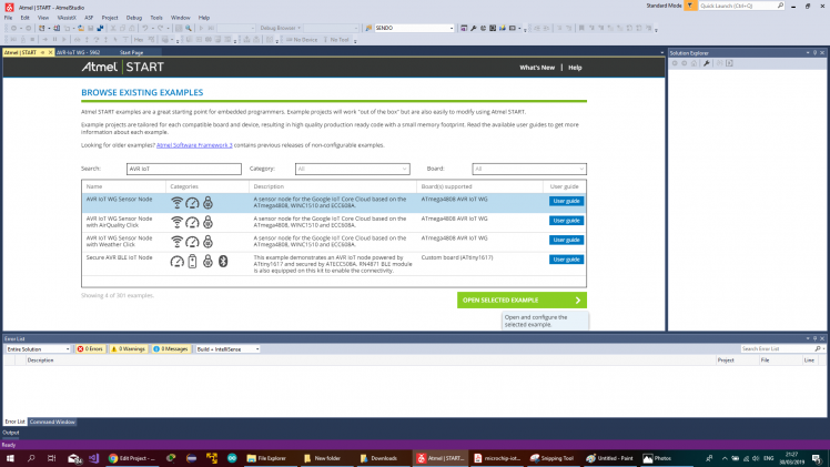
To program the board open Atmel Studio and open Atmel Start Example project.
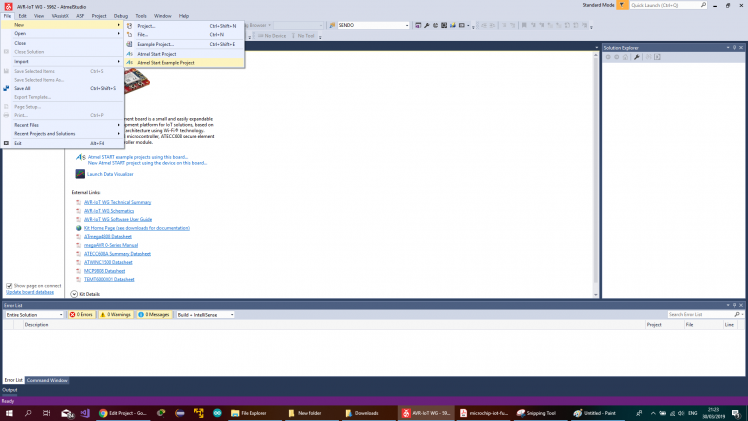
On the browser, search filter write AVR IoT and select AVR IoT Node.
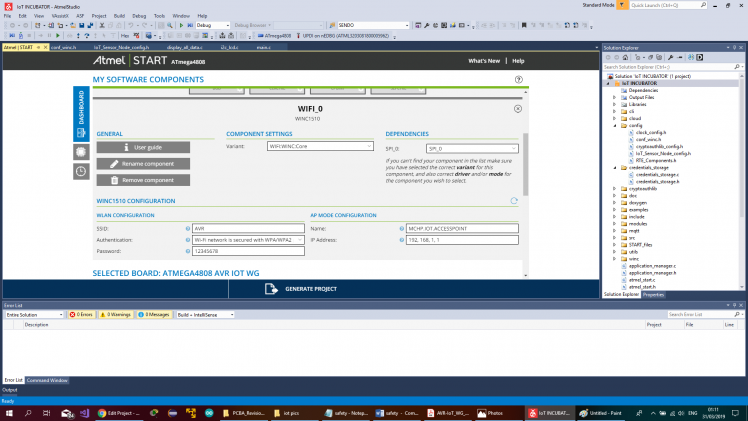
In the dash board select WiFi middelware.

And set up your default WiFi credentials.
On the left side, click on the PINMUX button (the chip icon under the dashboard button). And configure the RX, CX and RST pins as pefipheral IO RX pin, and as digital output CX and RST.
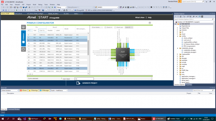
Please be aware to use the same names if you are going to use the code that I've uploaded to GitHub.
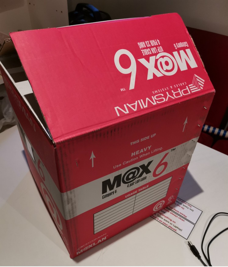
Take a good cardboard box.
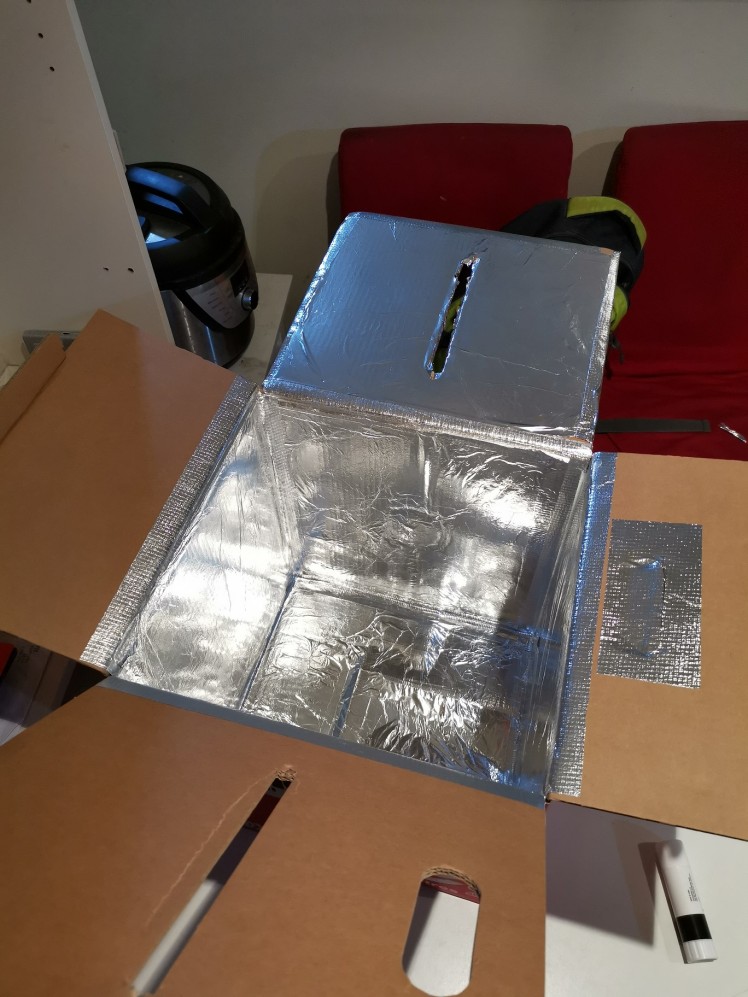
Shells the interior with aluminum, it will isolate the cardboard from the humidity, you can also build the incubator with another materials, for example using a plastic box.
On this case I'm using a 75W light bulb as a heater element, and a 5V USB fan it will be enough for that size of incubator, don't forget to make enough holes to let fresh air get it to avoid the CO2 levels increase.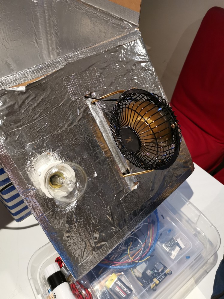
I'm using a mini ultrasonic humidifier to set up the humidity, it works incredibly good.
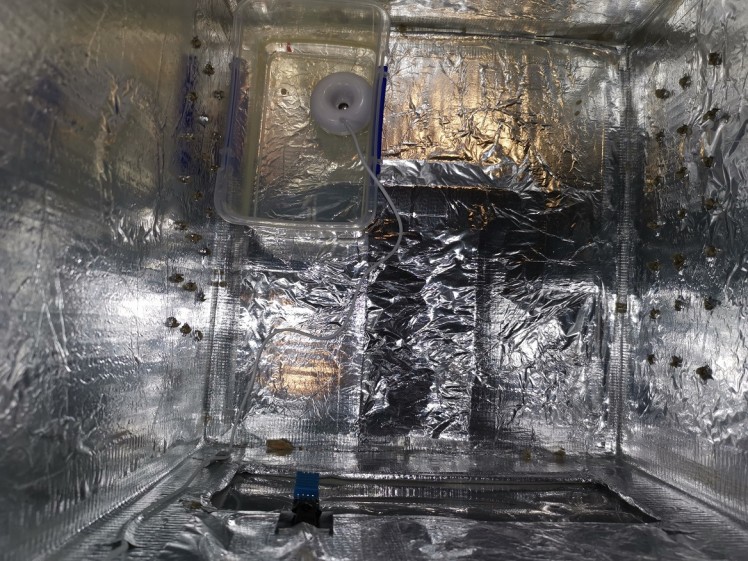
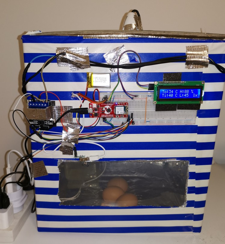
Once we have set in place the sensor, heating element, the fan and the humidifier we can make the connections and finish building the incubator. And this is final result.
Schematics and circuit diagrams
General connection diagram