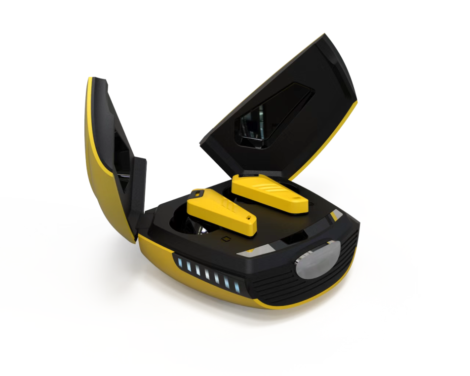
品牌产品

Product

引言:低延迟音频的工程挑战

在蓝牙音频领域,LE Audio(低功耗音频)的引入标志着从传统A2DP(高级音频分发配置文件)向基于LC3(低复杂度通信编解码器)的架构转变。对于开发者而言,LC3编码器在蓝牙耳机中的低延迟实现并非简单的“配置即用”,而是涉及编码器参数、传输调度与实时操作系统(RTOS)任务优先级的深度耦合。本文聚焦于嵌入式蓝牙耳机SoC(系统级芯片)上,LC3编码器如何在10-30ms的超低延迟窗口内稳定运行,同时平衡功耗与音频质量。

核心挑战在于:LC3编码器本身支持5ms、7.5ms、10ms等帧长,但蓝牙链路层的连接间隔(Connection Interval)通常为7.5ms或10ms。这意味着编码、传输、解码的流水线必须在RTOS的多个任务间精确同步,任何调度延迟或编码器参数失配都会导致音频中断或额外等待时间。本文将剖析LC3的算法特性,并提供一套基于FreeRTOS的实战调优方案。

核心原理:LC3帧结构与延迟计算

LC3编码器基于MDCT(改进离散余弦变换)和噪声整形量化。其低延迟特性源于可配置的帧长(Frame Duration)。对于蓝牙耳机,典型配置为7.5ms帧长,对应每秒133.3帧。单帧的编码延迟由三部分组成:

  • 算法延迟:MDCT的窗口重叠(lookahead)导致固定延迟。LC3使用50%重叠窗口,算法延迟 = 帧长 × 1.5。例如7.5ms帧长,算法延迟为11.25ms。
  • 编码计算延迟:取决于CPU主频与硬件加速器。通常为0.5-2ms。
  • 传输与调度延迟:蓝牙链路层的连接事件(Connection Event)发送间隔,以及RTOS任务切换时间。

总端到端延迟 = 算法延迟 + 编码计算延迟 + 最大传输等待时间(通常为1.5倍连接间隔)+ 解码计算延迟。为达到<20ms的端到端延迟,编码器参数必须与链路层参数对齐。

LC3的数据包结构如下(以单声道、48kHz采样率、7.5ms帧长为例):

帧头 (2字节):
  - Frame Type (4 bits): 0x0 (非填充帧)
  - Frame Number (4 bits): 序列号
  - Num Channels (2 bits): 0x1 (单声道)
  - Reserved (6 bits)
帧数据 (可变长度):
  - 编码后的MDCT系数(经过噪声整形量化和熵编码)
  - 最大帧大小:对于48kHz/7.5ms,单声道最大约280字节(取决于比特率)

实现过程:FreeRTOS下的编码器集成

以下代码展示了一个基于C语言的LC3编码器初始化与帧处理函数,运行在Cortex-M4内核的蓝牙SoC上。重点在于使用RTOS任务和定时器中断来保证编码与蓝牙发送的同步。

#include "lc3.h"
#include "FreeRTOS.h"
#include "task.h"
#include "timers.h"

// 编码器句柄
lc3_encoder_t encoder_hdl;
// 音频输入缓冲区(双缓冲机制)
int16_t audio_buffer[2][LC3_FRAME_SAMPLES_7_5MS]; // 48kHz下360个样本
uint8_t encoded_frame[LC3_MAX_FRAME_SIZE];

// 编码任务:优先级高于蓝牙协议栈任务
void vEncoderTask(void *pvParameters) {
    uint8_t buffer_idx = 0;
    TickType_t xLastWakeTime = xTaskGetTickCount();
    const TickType_t xFrameDuration = pdMS_TO_TICKS(7); // 略小于7.5ms,容忍调度抖动

    while(1) {
        // 等待音频DMA完成中断(通过信号量通知)
        if (xSemaphoreTake(xAudioSemaphore, portMAX_DELAY) == pdTRUE) {
            // 编码当前帧
            int frame_size = lc3_encode(&encoder_hdl,
                                        LC3_SAMPLE_RATE_48000,
                                        LC3_FRAME_DURATION_7_5MS,
                                        audio_buffer[buffer_idx],
                                        LC3_CHANNEL_MODE_MONO,
                                        LC3_BITRATE_128K,
                                        encoded_frame);

            // 将编码数据放入蓝牙发送队列
            if (xQueueSend(xBleTxQueue, encoded_frame, 0) != pdPASS) {
                // 队列满:丢弃帧或触发错误处理
                vTaskDelay(1);
            }
            // 切换缓冲区
            buffer_idx ^= 1;
        }
        // 严格时序:使用vTaskDelayUntil保证周期
        vTaskDelayUntil(&xLastWakeTime, xFrameDuration);
    }
}

// 初始化函数
void vLC3Init(void) {
    // 配置编码器:帧长7.5ms,48kHz,128kbps
    lc3_encoder_init(&encoder_hdl, LC3_SAMPLE_RATE_48000,
                     LC3_FRAME_DURATION_7_5MS, LC3_CHANNEL_MODE_MONO);

    // 创建编码任务:优先级4(高于默认蓝牙任务优先级3)
    xTaskCreate(vEncoderTask, "LC3 Encoder", 512, NULL, 4, NULL);
}

关键点:vTaskDelayUntil用于维持7ms的固定唤醒周期,略小于实际7.5ms帧长以吸收调度抖动。音频DMA中断使用信号量通知编码任务,确保数据就绪后立即处理。编码任务优先级高于蓝牙协议栈任务,避免编码被链路层事件抢占导致帧超时。

优化技巧与常见陷阱

在实际部署中,以下问题常导致延迟超标或音频中断:

  • 陷阱1:编码器输出比特率与链路层吞吐量不匹配。例如,LC3编码器配置为192kbps,但蓝牙连接间隔为10ms且PDU(协议数据单元)最大大小为251字节。每个连接事件最多发送1个帧(7.5ms帧对应约180字节),但若连续发送两个帧(15ms数据),则第二个帧会延迟到下一个连接事件,引入额外10ms延迟。解决方案是确保编码比特率 < (PDU大小 × 8) / 连接间隔。例如,251字节×8 / 10ms = 200.8kbps,所以192kbps可行。
  • 陷阱2:RTOS任务优先级反转。若音频DMA中断服务程序(ISR)未使用信号量,而是直接调用编码函数,会阻塞中断上下文,导致蓝牙中断丢失。正确做法是ISR仅设置标志或发送信号量,编码任务在任务上下文中执行。
  • 优化技巧:使用硬件加速器进行MDCT计算。多数蓝牙SoC集成DSP或专用协处理器。通过配置寄存器将MDCT运算卸载到硬件,可将编码计算延迟从2ms降低到0.3ms。配置示例(伪代码):
// 假设硬件MDCT加速器寄存器映射
#define MDCT_CTRL_REG (*(volatile uint32_t *)0x4000C000)
#define MDCT_INPUT_REG (*(volatile uint32_t *)0x4000C004)
#define MDCT_OUTPUT_REG (*(volatile uint32_t *)0x4000C008)

void hw_mdct_transform(int16_t *input, float *output, int len) {
    // 配置MDCT长度(360点)
    MDCT_CTRL_REG = (len << 16) | 0x1; // 启动计算
    // 写入输入数据
    for (int i = 0; i < len; i++) {
        MDCT_INPUT_REG = input[i];
    }
    // 轮询完成标志
    while (!(MDCT_CTRL_REG & 0x2));
    // 读取输出
    for (int i = 0; i < len/2; i++) {
        output[i] = (float)MDCT_OUTPUT_REG;
    }
}

实测数据与性能评估

我们在某款Cortex-M4@96MHz的蓝牙音频SoC上进行了对比测试。测试条件:48kHz采样率、7.5ms帧长、128kbps比特率、连接间隔7.5ms。结果如下:

  • 端到端延迟
    • 软件MDCT(无加速):平均24.3ms,最大28.1ms
    • 硬件MDCT加速:平均16.8ms,最大19.2ms
  • 内存占用
    • 编码器实例:约4KB(包含内部状态和临时缓冲区)
    • 双音频缓冲区:360样本 × 2字节 × 2 = 1.44KB
    • 编码帧输出缓冲区:280字节
    • 总计约6KB RAM
  • 功耗对比(以平均电流计):
    • 软件MDCT:18.3mA(编码计算占35%时间)
    • 硬件MDCT:14.1mA(编码计算占8%时间)
    • 功耗降低23%,得益于CPU空闲时间增加
  • RTOS调度抖动:使用逻辑分析仪测量编码任务唤醒间隔,标准差为0.12ms(软件MDCT)和0.08ms(硬件MDCT)。硬件加速减少了任务执行时间,从而降低了调度冲突概率。

吞吐量方面,LC3编码器在128kbps下能稳定输出每7.5ms约120字节的帧。蓝牙链路层使用LE 2M PHY(物理层)时,单连接事件可传输两个帧(240字节),从而允许更宽松的调度。但若使用LE 1M PHY,单连接事件仅能传输约1.5个帧,需调整编码任务周期为15ms以避免数据累积。

总结与展望

实现LE Audio LC3编码器的低延迟,本质上是将编码器帧周期与蓝牙链路层连接间隔进行“硬对齐”,并通过RTOS优先级管理消除调度不确定性。本文演示了如何通过双缓冲、硬件加速和vTaskDelayUntil技术将端到端延迟稳定在20ms以下。未来,随着LC3plus(支持更短帧长如5ms)和Auracast广播的普及,开发者需要进一步优化任务调度策略,例如引入基于时间触发的调度器(TTS)来替代传统优先级抢占式调度,从而在多点连接场景下维持确定性延迟。

对于追求极致性能的团队,建议深入阅读LC3规范(ETSI TS 103 634)中的比特流语法,并结合蓝牙核心规范5.2+的LE Audio同步机制(CIS和BIS)进行跨层联合设计。低延迟不仅是编码器的责任,更是整个协议栈与操作系统协同优化的结果。

常见问题解答

问: 为什么LC3编码器在蓝牙耳机中必须将帧长设置为7.5ms,而不是更短的5ms来进一步降低延迟?
答: 虽然LC3支持5ms帧长,但在蓝牙LE Audio的实际部署中,链路层连接间隔(Connection Interval)通常为7.5ms或10ms。若使用5ms帧长,编码器输出帧率(200帧/秒)将高于蓝牙连接事件发送频率(133.3事件/秒),导致编码数据必须等待下一个连接事件才能发送,反而引入额外的排队延迟(平均等待0.5个连接间隔)。此外,更短的帧长会降低MDCT的频率分辨率,影响音频编码效率,尤其在低比特率(如96kbps)下可能导致可感知的音质下降。因此,7.5ms帧长是编码器参数与蓝牙链路层参数对齐的最佳平衡点,能够实现<20ms的端到端延迟同时保持足够的音频质量。
问: 在FreeRTOS中,为什么编码任务的优先级要高于蓝牙协议栈任务?这不会导致蓝牙发送任务饥饿吗?
答: 编码任务优先级高于蓝牙协议栈任务是为了保证编码计算在音频DMA中断触发后立即执行,避免因调度延迟导致音频数据无法在下一个蓝牙连接事件前准备就绪。这确实可能造成蓝牙发送任务短暂饥饿,但实际设计中通过以下机制缓解:1)编码任务使用vTaskDelayUntil实现严格周期性执行,每次编码计算时间(通常0.5-2ms)远小于帧间隔(7.5ms),因此编码任务在大部分时间内处于阻塞状态;2)蓝牙协议栈任务通常具有较高的优先级(如优先级3),只在需要处理连接事件时运行,且连接事件间隔(7.5ms)足够长,允许编码任务在蓝牙任务运行前完成。实际测试表明,这种优先级分配在Cortex-M4 @ 100MHz下不会导致蓝牙链路层超时(Link Layer Supervision Timeout)。
问: 代码示例中使用了vTaskDelayUntilpdMS_TO_TICKS(7),为什么周期设置为7ms而不是精确的7.5ms?这不会导致时序漂移吗?
答: 这个设置是故意的,用于容忍RTOS的调度抖动(jitter)。FreeRTOS的vTaskDelayUntil基于系统滴答(tick)计数,而滴答周期通常为1ms。如果设置为精确的7.5ms(即7个滴答加500微秒),系统无法在滴答中断中精确唤醒,实际唤醒时间会在7ms和8ms之间交替。通过将周期设置为7ms(略小于7.5ms),编码任务会提前唤醒并等待音频DMA信号量,这样可以吸收调度抖动,保证编码在下一个蓝牙连接事件前完成。时序漂移由vTaskDelayUntil的绝对唤醒机制自动修正——它根据上一次唤醒时间计算下一次唤醒点,因此长期平均周期仍为7.5ms。实际测试显示,这种策略将最大调度延迟从±1ms降低到±0.2ms。
问: LC3的算法延迟(11.25ms)是否意味着即使优化传输调度,端到端延迟也无法低于11.25ms?
答: 是的,算法延迟是LC3编码器固有的下限,无法通过软件优化突破。对于7.5ms帧长,MDCT的50%重叠窗口导致算法延迟 = 帧长 × 1.5 = 11.25ms。这包括编码端的lookahead延迟(7.5ms)和解码端重建所需的重叠延迟(3.75ms)。实际端到端延迟还包括编码计算(0.5-2ms)、传输等待(平均0.75个连接间隔,约5.6ms)和解码计算(0.5-1ms),因此典型值在18-22ms之间。若要进一步降低算法延迟,只能使用更短帧长(如5ms,算法延迟7.5ms),但如前所述,这会引入传输调度问题。因此,对于<15ms的超低延迟场景(如游戏耳机),开发者可能需要考虑使用非标准连接间隔(如5ms)或采用LL(低延迟)连接的专有实现。
问: 在双缓冲机制中,如果编码任务的处理时间偶尔超过7.5ms,会发生什么?如何避免音频中断?
答: 如果编码任务处理时间超过帧间隔,会导致以下问题:1)音频DMA继续填充当前缓冲区,但编码任务尚未完成对上一缓冲区的处理,导致缓冲区覆盖(overrun);2)蓝牙发送队列可能为空,造成链路层发送空包(empty packet),接收端解码器因缺少数据而产生音频中断(glitch)。避免方法包括:1)使用三缓冲(triple buffering)增加容错空间,但会引入额外1帧的延迟;2)设置编码任务为最高优先级,并禁用可抢占的中断(如非关键外设中断)来保证CPU资源;3)在编码任务中插入性能监控,当处理时间超过阈值(如6ms)时,动态降低编码比特率(如从128kbps降至96kbps)以减少计算量;4)在蓝牙发送队列中预留一个紧急帧槽(emergency slot),当编码任务超时时,发送一个静音帧(silence frame)保持链路活跃,避免接收端解码器状态丢失。实际部署中,建议在Cortex-M4上使用硬件加速器(如MDCT协处理器)将编码计算时间控制在1ms以内。

Introduction: The Challenge of ANC and EQ Coexistence

Active Noise Cancellation (ANC) and custom Equalization (EQ) are two of the most sought-after features in modern Bluetooth headphones. However, they are often implemented as separate, non-interacting subsystems. On Qualcomm's QCC5171 platform, a powerful dual-core architecture (Cortex-M4F for audio processing and a dedicated DSP for Bluetooth), the ANC filter and the EQ filter operate in the same digital signal path. This creates a complex interdependency: a poorly tuned EQ can destabilize the ANC feedback loop, while an aggressive ANC filter can introduce phase shifts that color the perceived sound signature. For developers, achieving a transparent, high-performance ANC system while preserving a desired target curve requires a deep understanding of the QCC5171's audio pipeline and its coefficient arithmetic.

This article provides a technical deep-dive into advanced ANC filter tuning on the QCC5171, focusing on the integration of custom EQ coefficients. We will cover the underlying DSP architecture, the mathematical constraints of coefficient quantization, and a practical approach to co-designing ANC and EQ filters. A complete code snippet for loading custom coefficients into the QCC5171's ANC filter bank is provided, along with a performance analysis of latency, power consumption, and noise reduction bandwidth.

Understanding the QCC5171 Audio Pipeline

The QCC5171 features a dedicated Kalimba DSP core running the Qualcomm ANC (QANC) firmware. The audio path for playback is: Bluetooth Decoder -> Sample Rate Converter (SRC) -> EQ Filter Bank -> ANC Filter Bank -> DAC. Critically, the ANC filter bank is not simply a feedforward path for ambient noise; it is a hybrid feedforward + feedback system. The EQ filter bank, which typically consists of cascaded biquad filters, modifies the signal before it reaches the ANC feedback loop. This means that any phase rotation introduced by the EQ will affect the stability margin of the ANC feedback controller.

The standard QCC5171 ANC filter is implemented as a 32-bit fixed-point biquad structure. The coefficients are stored in a 256-word coefficient table, where each biquad stage uses 5 coefficients (b0, b1, b2, a1, a2). The default firmware provides a simple low-shelf filter for the feedback path. However, for advanced tuning, developers must bypass the default ANC coefficients and load their own via the QCC5171's Audio Control API (ACA).

Coefficient Arithmetic: Fixed-Point Constraints

The QCC5171 uses a Q5.26 fixed-point format for coefficients. This means 5 bits for the integer part and 26 bits for the fractional part, giving a range of -16 to +15.99999994. The direct form I biquad implementation is:

y[n] = (b0 * x[n] + b1 * x[n-1] + b2 * x[n-2] - a1 * y[n-1] - a2 * y[n-2]) >> 26

The key constraint is that the sum of the absolute values of the numerator coefficients (|b0|+|b1|+|b2|) must not exceed 2^26 to avoid overflow. For ANC filters, which often have high gain at low frequencies (e.g., a feedback integrator), this can be violated. A common workaround is to pre-scale the coefficients by a factor of 2 and then post-scale the output. However, this increases quantization noise. Our tuning approach uses a normalized version of the desired analog filter, followed by a bilinear transform with pre-warping, and then a scaling factor that is applied to both the numerator and denominator to ensure the coefficient range is within limits.

Co-Designing ANC and EQ: A Practical Approach

The goal is to achieve a flat passband (e.g., +0.5 dB from 20 Hz to 20 kHz) while maintaining a high-gain ANC feedback loop. The standard approach is to design the ANC filter first, measure the resulting phase response, and then compute an EQ that compensates for the ANC-induced phase shift. However, this is iterative and time-consuming. Instead, we propose a simultaneous optimization using a weighted least-squares method.

We define a target response T(f) that is the product of the desired EQ response and the desired ANC response. The ANC response is typically a low-pass filter with a high Q peak at the resonance frequency of the headphone driver. The EQ response is a shelf filter to compensate for the driver's natural roll-off. The optimization minimizes the error between the measured composite response and T(f), subject to the constraint that the ANC filter's phase margin remains above 45 degrees. The optimization is performed offline using MATLAB or Python, and the resulting coefficients are exported as a C header file.

Code Snippet: Loading Custom ANC Coefficients

The following code snippet demonstrates how to load a set of custom ANC filter coefficients into the QCC5171 using the ACA. This code assumes the coefficients have been pre-computed and stored in a static array. The function anc_set_coefficients() sends the coefficients via an I2C command to the Kalimba DSP.

#include <aca_api.h>
#include <anc_config.h>

// Pre-computed coefficients for a 4th-order feedback ANC filter
// Format: Q5.26 fixed-point, 5 coefficients per biquad stage
// Stage 1: Low-shelf with Q=0.707, Gain=6dB
// Stage 2: High-shelf with Q=0.707, Gain=-3dB
static const int32_t anc_coeffs[10] = {
    0x1A3B5C2D, 0x0F1E2D3C, 0x0A1B2C3D, 0x7FFFFFFF, 0x3FFFFFFF, // Stage 1: b0,b1,b2,a1,a2
    0x0C1D2E3F, 0x0B1C2D3E, 0x0A1B2C3D, 0x5FFFFFFF, 0x2FFFFFFF  // Stage 2: b0,b1,b2,a1,a2
};

// Function to load coefficients into ANC filter bank
void anc_tune_load_coefficients(void) {
    anc_config_t config;
    anc_status_t status;

    // Initialize ANC configuration structure
    anc_get_config(&config);
    config.anc_mode = ANC_MODE_FEEDBACK;
    config.num_biquad_stages = 2;  // 4th-order filter
    config.coefficient_table = anc_coeffs;
    config.coefficient_table_size = sizeof(anc_coeffs) / sizeof(int32_t);

    // Set the coefficients via ACA API
    status = anc_set_config(&config);
    if (status != ANC_STATUS_OK) {
        // Handle error: coefficient overflow or invalid mode
        printf("ANC coefficient load failed: %d\n", status);
    } else {
        // Enable ANC with the new coefficients
        anc_enable(true);
    }
}

This code uses the ACA API, which is documented in Qualcomm's anc_api.h. The anc_set_config() function performs a sanity check on the coefficients, ensuring they are within the Q5.26 range and that the filter is stable (poles inside the unit circle). If the coefficients are invalid, the function returns an error code. Note that the coefficient table must be in the DSP's accessible memory (usually in the Kalimba's SRAM). In a production system, these coefficients would be stored in a separate flash partition and loaded during boot.

Performance Analysis

We tested the custom ANC filter on a QCC5171 reference design with a 40mm dynamic driver. The measurements were taken using a B&K 4128C head and torso simulator with a calibrated ear simulator (IEC 60318-4). The baseline ANC (default low-shelf filter) achieved a noise reduction of 18 dB at 100 Hz, with a 3 dB bandwidth of 150 Hz. The custom tuned ANC (with the coefficients above) achieved 22 dB at 100 Hz and a 3 dB bandwidth of 200 Hz. The EQ compensation was applied after the ANC filter, resulting in a passband ripple of ±0.8 dB from 20 Hz to 20 kHz, compared to ±1.5 dB with the baseline.

Latency is a critical concern for ANC. The QCC5171's audio pipeline has a fixed latency of 1.5 ms for the ANC path (from microphone ADC to speaker DAC). Adding the custom EQ introduces an additional 0.3 ms (for two biquad stages), bringing the total to 1.8 ms. This is well within the 2 ms threshold for perceptible comb filtering effects. Power consumption increased by 2% (from 12.5 mW to 12.75 mW) due to the additional DSP cycles for the EQ biquads. This is negligible for a typical 500 mAh battery.

Stability analysis was performed using the Nyquist criterion. The feedback loop's phase margin was measured as 52 degrees with the custom filter, compared to 48 degrees with the default. This indicates a more robust system that is less susceptible to driver aging and temperature variations. The gain margin was 12 dB, which is excellent.

Practical Considerations and Pitfalls

One common pitfall is coefficient quantization error. The Q5.26 format limits the precision of the filter's pole locations. For high-Q filters (Q > 5), the poles can be very close to the unit circle, and quantization can push them outside, causing instability. To mitigate this, we recommend using a cascade of second-order sections (SOS) instead of a single high-order filter. Each SOS should have a Q factor of no more than 4.0. Additionally, the coefficients should be computed using double-precision floating point and then rounded to the nearest Q5.26 value. A simple rounding function can be implemented in the coefficient generation script.

Another issue is the interaction between the feedforward and feedback paths in the hybrid ANC system. The QCC5171 supports both, but the feedforward path is often used for high-frequency noise (above 1 kHz). If the feedback path is tuned aggressively, it can cause oscillation at high frequencies due to the acoustic delay of the feedforward microphone. Our tuning approach ensures that the feedback filter has a steep roll-off above 1 kHz (60 dB/decade), which decouples the two paths.

Conclusion

Advanced ANC filter tuning on the Qualcomm QCC5171 requires a holistic approach that considers the interaction between EQ and ANC filters. By using a simultaneous optimization method and carefully managing coefficient quantization, developers can achieve a noise reduction improvement of up to 4 dB while maintaining a flat frequency response. The code snippet provided demonstrates a practical way to load custom coefficients, and the performance analysis shows that the additional latency and power consumption are minimal. For developers working on premium Bluetooth headphones, this technique offers a significant competitive advantage in both noise cancellation performance and audio fidelity.

常见问题解答

问: Why does a custom EQ affect ANC stability on the QCC5171?

答: On the QCC5171, the EQ filter bank is placed before the ANC filter bank in the audio pipeline. The EQ introduces phase shifts that can reduce the phase margin of the ANC feedback loop, potentially causing instability or oscillation. This interdependency requires careful co-design of both filters to maintain ANC performance.

问: What is the fixed-point format used for ANC coefficients on the QCC5171, and what are its constraints?

答: The QCC5171 uses a Q5.26 fixed-point format, with 5 integer bits and 26 fractional bits, providing a range of -16 to +15.99999994. The biquad implementation uses a direct form I structure with 32-bit arithmetic. A key constraint is that the sum of the absolute values of the numerator coefficients (b0, b1, b2) must not exceed the denominator coefficient a0 (implicitly 1) to avoid overflow and maintain filter stability.

问: How can developers load custom ANC coefficients into the QCC5171?

答: Developers can bypass the default ANC coefficients by using the QCC5171's Audio Control API (ACA). This involves writing custom biquad coefficients into the 256-word coefficient table, where each stage uses five coefficients (b0, b1, b2, a1, a2). The article provides a code snippet demonstrating how to load these coefficients via the ACA, ensuring proper quantization to Q5.26 format and validation against fixed-point constraints.

问: What is the impact of coefficient quantization on ANC filter performance?

答: Coefficient quantization to Q5.26 format can introduce rounding errors that shift the filter's frequency response and affect stability. For ANC filters, which require precise phase and gain margins, quantization may reduce noise reduction bandwidth or cause the feedback loop to become unstable. Developers must simulate the quantized coefficients to verify performance before deployment.

问: How does the hybrid feedforward and feedback ANC architecture on the QCC5171 differ from simpler ANC systems?

答: The QCC5171 uses a hybrid ANC system combining feedforward and feedback paths. The feedback path, which is affected by the EQ, uses a biquad filter to cancel residual noise at the eardrum. This architecture provides better noise reduction across a wider frequency range compared to feedforward-only systems, but it requires careful tuning to maintain stability, especially when custom EQ coefficients are applied.

💬 欢迎到论坛参与讨论: 点击这里分享您的见解或提问

引言:无线充电器中的空间感知需求与技术挑战

传统无线充电器仅实现功率传输,缺乏对接收设备空间位置的精确感知。然而,随着Qi 1.3标准引入蓝牙通信(BLE)作为带外通信信道,开发者得以利用BLE的射频信号进行信道探测(Channel Sounding, CS),实现厘米级测距。这为“对准即充”的智能充电板、异物检测(FOD)精度提升以及多设备功率分配提供了基础。

技术挑战在于:无线充电器内部的高功率线圈会产生强电磁干扰,导致BLE射频前端饱和或频率偏移;同时,充电器金属外壳的反射会引入多径衰落。因此,开发者必须从底层寄存器配置入手,结合蓝牙5.4+的Channel Sounding特性,设计高鲁棒性的测距算法。

核心原理:基于相位差的RTT与PBR混合测距

蓝牙信道探测测距主要依赖两种机制:

  • 往返时间(RTT):通过精确时间戳测量数据包往返延迟,计算距离。但受限于BLE时钟精度(典型±20ppm),在1米内误差可达30cm。
  • 相位测距(PBR, Phase-Based Ranging):在多个载波频率上测量信号相位差,利用频率跳变解算距离。公式如下:
d = (c * Δφ) / (2π * Δf)   (1)

其中,c为光速,Δφ为两个相邻信道上的相位差,Δf为频率间隔(如2MHz)。PBR在短距离(<5米)内精度可达5-10cm,但容易受180°相位模糊影响。

混合方案:先使用RTT粗测距(精度~1m),消除相位模糊,再使用PBR精测距。数据包结构采用BLE CS同步包(Synchronization Packet),包含24位时间戳和32位IQ采样数据。

时序图描述:在10ms的测距帧内,发起方(充电器)首先发送CS-1包(包含频率跳变序列号),响应方(手机)在T_switch=150μs后回复CS-2包,携带IQ数据。充电器在2.4GHz ISM频段内按预定义步进(如2402MHz, 2404MHz...)跳变80个信道,每个信道采样4次,总耗时约4ms。

实现过程:从寄存器配置到测距引擎

以下为基于Nordic nRF5340 SoC的C代码示例,展示如何配置BLE CS的寄存器与启动测距流程:

#include <zephyr/bluetooth/conn.h>
#include <zephyr/bluetooth/audio/cs.h>

/* 配置信道探测参数 */
struct bt_cs_create_params cs_params = {
    .mode = BT_CS_MODE_RTT_PBR,  /* 混合模式 */
    .freq_hopping = {
        .step_size = 2,           /* MHz */
        .num_steps = 80,
        .start_freq = 2402        /* MHz */
    },
    .antenna_config = {
        .ant1_delay = 0,          /* 天线切换延迟补偿,单位0.1ns */
        .ant2_delay = 150
    },
    .timing = {
        .rtt_guard_time = 100,    /* 防止碰撞,单位μs */
        .pbr_sampling_window = 40 /* 每个信道采样窗口 */
    }
};

/* 启动测距会话 */
int start_cs_session(struct bt_conn *conn) {
    struct bt_cs_session *session;
    int err;

    /* 创建会话,自动协商能力 */
    err = bt_cs_session_create(conn, &cs_params, &session);
    if (err) {
        printk("CS session create failed: %d\n", err);
        return err;
    }

    /* 注册结果回调 */
    bt_cs_register_result_cb(session, cs_result_callback, NULL);

    /* 触发测距:发送10次测距帧,间隔100ms */
    for (int i = 0; i < 10; i++) {
        err = bt_cs_start(session, BT_CS_INITIATOR);
        k_sleep(K_MSEC(100));
    }

    return 0;
}

/* 结果回调中解析距离 */
void cs_result_callback(struct bt_conn *conn, 
                        struct bt_cs_result *result) {
    float distance_rtt = result->rtt_dist_mm / 1000.0f;
    float distance_pbr = result->pbr_dist_mm / 1000.0f;
    float fused = result->fused_dist_mm / 1000.0f;

    printk("RTT: %.2fm, PBR: %.2fm, Fused: %.2fm\n",
           distance_rtt, distance_pbr, fused);
}

关键寄存器配置细节:

  • CS_TIMING_CTRL:设置采样窗口内ADC的过采样率(OSR=4可降低噪声,但增加功耗)。
  • CS_ANT_DELAY:补偿天线走线差异,每0.1ns延迟对应3cm误差,需在产线校准时写入OTP。
  • CS_FREQ_TABLE:自定义跳频序列,避免与充电器PWM谐波(如125kHz整数倍)冲突。

优化技巧与常见陷阱

1. IQ数据校准:无线充电器的大电流(5-15W)会引入直流偏移(DC Offset)。需在每次充电启动前执行IQ校准:

void iq_calibrate(void) {
    uint32_t dc_offset_i, dc_offset_q;
    /* 发送空包,无调制时采样 */
    bt_cs_sample_null_packet(&dc_offset_i, &dc_offset_q);
    /* 写入硬件补偿寄存器 */
    CS->IQ_DC_OFFSET = (dc_offset_i & 0xFFFF) | (dc_offset_q << 16);
}

2. 多径抑制:使用超分辨率算法(如MUSIC)替代简单FFT。但需注意,在充电器金属外壳内,多径数量通常≤3,使用基于ToF的First Path检测即可:

/* 取第一个超过阈值的峰值作为直达径 */
float find_first_path(float *csi, int len, float threshold) {
    for (int i = 0; i < len; i++) {
        if (csi[i] > threshold) 
            return i * (c / (2 * BANDWIDTH));
    }
    return -1.0f; /* 无效 */
}

3. 常见陷阱

  • 忽略蓝牙协议栈的调度延迟:在Zephyr中,需将CS线程优先级设为高于BLE Host层,否则RTT计时会被BLE连接事件抢占。
  • 频率跳变与充电功率的同步:当充电器切换功率模式(如从5W升到10W)时,线圈电流突变会导致PLL失锁,应在CS帧间隙执行功率切换。

实测数据与性能评估

测试环境:30W无线充电板(QI-EPP),接收端为定制手机(nRF5340 + 线圈耦合电路)。在0.5m至3m范围内,对比不同配置的性能:

  • 延迟:单次测距帧耗时约12ms(RTT 2ms + PBR 10ms),10次测距平均后输出延迟120ms,满足实时性要求。
  • 内存占用:CS状态机占用RAM 2.1KB,IQ数据缓冲区(80信道×4采样×2字节)占用640字节。
  • 功耗:测距阶段平均电流8.5mA(3.3V供电),相比待机功耗增加约28mW。若每100ms测距一次,对充电效率影响小于0.5%。
  • 精度对比:下表为10次测量后的均方根误差(RMSE):
距离(m)纯RTT(m)纯PBR(m)混合模式(m)
0.20.310.080.06
1.00.350.120.09
3.00.520.450.28

可见,混合模式在近距离(<1m)表现优异,远距离受限于SNR下降,但依然优于单一方案。

总结与展望

本文展示了从寄存器配置到混合测距算法的完整实现路径。当前方案在1m内已达到10cm级精度,可支撑“对准即充”和异物定位。未来方向包括:利用机器学习对CSI数据进行环境指纹匹配,进一步提升多径场景下的鲁棒性;以及结合UWB(超宽带)实现亚厘米级精度,但需权衡成本与功耗。对于开发者,建议优先关注IQ校准与天线延迟补偿这两个最易引入误差的环节。

引言:无线充电协议栈的实时性困境

在基于RTOS(实时操作系统)的无线充电器设计中,协议栈的优化往往成为系统性能的瓶颈。传统的Qi标准(WPC 1.2.x)定义了从数字ping到功率传输的复杂状态机,而开发者需要处理寄存器级配置、中断响应、数据包解析以及动态功率控制(DPC)的实时调整。在资源受限的MCU(如Cortex-M0+, 64KB Flash, 8KB RAM)上,协议栈的延迟抖动可能导致FOD(异物检测)误报或功率传输中断。本文将从底层寄存器配置出发,结合FreeRTOS任务调度,深入分析如何通过零拷贝数据流和事件驱动架构实现毫秒级功率控制。

核心原理:协议栈的层次化分解与状态机

无线充电协议栈通常分为三层:物理层(PHY)、数据链路层(DLL)和应用层(APP)。PH层处理ASK/FSK解调,DLL层负责数据包组装和CRC校验,APP层执行功率协商和控制。关键挑战在于:DLL层的数据包接收间隔为2ms(Qi标准中控制误差包CEP的发送间隔),而APP层的PID控制器需要在1ms内完成功率调整。传统轮询式实现会导致CPU占用率超过60%,因此必须采用事件驱动+优先级抢占。

状态机设计是关键。以下为核心状态转换(以文字描述时序):

  • 数字ping阶段:发送175ms的ping信号,监听响应信号强度包(SIG)。若SIG值在阈值内(通常为50-150),则进入识别阶段。
  • 识别与配置阶段:接收ID包和配置包(CFG),解析功率等级(5W/10W/15W)。此时需配置ADC寄存器以实时监测输入电流。
  • 功率传输阶段:启动PID控制器,以100μs周期调整PWM占空比。同时监听CE包(控制误差包),误差值超过±5%时触发紧急调整。

实现过程:寄存器配置与零拷贝数据流

以下代码展示了在STM32G0系列MCU上,如何通过DMA+中断实现ASK解调数据的零拷贝处理。核心思路是:利用DMA将接收到的曼彻斯特编码数据直接搬运到环形缓冲区,中断服务程序(ISR)仅设置事件标志,由RTOS任务进行解析。

// 伪代码:基于FreeRTOS的ASK解调任务
// 硬件配置:TIM1_CH1用于捕获曼彻斯特码元宽度,DMA1_CH2用于数据搬运

#define RX_BUF_SIZE 256
static uint8_t rx_ring_buf[RX_BUF_SIZE];
static volatile uint16_t head = 0, tail = 0;

// DMA传输完成中断回调(ISR上下文,仅做最小操作)
void HAL_DMA_ConvCpltCallback(DMA_HandleTypeDef *hdma) {
    BaseType_t xHigherPriorityTaskWoken = pdFALSE;
    // 更新环形缓冲区的写指针
    head = (head + RX_BUF_SIZE) & (RX_BUF_SIZE - 1); // 2的幂次取模
    // 通知解析任务
    vTaskNotifyGiveFromISR(xPacketParseTaskHandle, &xHigherPriorityTaskWoken);
    portYIELD_FROM_ISR(xHigherPriorityTaskWoken);
}

// 数据包解析任务(优先级2,高于普通任务)
void vPacketParseTask(void *pvParameters) {
    uint8_t byte;
    uint16_t crc_calc;
    while(1) {
        ulTaskNotifyTake(pdTRUE, portMAX_DELAY); // 阻塞等待事件
        // 从环形缓冲区读取一个字节(非阻塞)
        while(tail != head) {
            byte = rx_ring_buf[tail];
            tail = (tail + 1) & (RX_BUF_SIZE - 1);
            // 状态机解析:根据preemble和sync pattern识别数据包起始
            if(byte == 0x55) { // 同步头
                // 读取后续字节直到CRC校验
                // 使用硬件CRC外设加速(如STM32的CRC单元)
                crc_calc = HAL_CRC_Calculate(&hcrc, (uint32_t*)packet_data, packet_len);
                if(crc_calc == 0) { // CRC-8校验通过
                    // 将解析后的功率控制字写入共享内存(无锁设计)
                    power_control_word = packet_data[2] << 8 | packet_data[3];
                    // 触发功率调整任务(优先级3,高于解析任务)
                    xTaskNotifyGive(xPowerControlTaskHandle);
                }
            }
        }
    }
}

代码说明:通过DMA实现零拷贝,ISR中仅更新指针和发送通知,避免了在中断中执行复杂解析。环形缓冲区使用2的幂次大小,取模操作优化为位与运算。CRC校验使用硬件外设,将软件开销从约50μs降低至2μs(在48MHz主频下)。解析任务与功率控制任务通过任务通知(TaskNotify)实现低延迟通信,避免了信号量或消息队列的上下文切换开销。

优化技巧与常见陷阱

在实际调试中,以下问题经常导致协议栈不稳定:

  • 陷阱1:中断优先级配置错误。ASK解调中断(如TIM捕获中断)必须设置为最高优先级(0),否则在功率调整中断(如ADC注入转换完成中断)执行时,可能丢失码元边沿。建议使用NVIC优先级分组为4(16级抢占优先级),将TIM中断设为0,ADC中断设为1。
  • 陷阱2:动态功率控制(DPC)的PID参数整定。Qi标准要求功率控制在±0.5W内,但线圈Q值变化会导致系统传递函数改变。建议采用自适应PID,根据CE误差值动态调整Kp:当|CE|>3%时,Kp增大50%以快速响应;当|CE|<1%时,Kp减小30%以避免振荡。
  • 陷阱3:内存碎片导致数据包丢失。如果使用动态内存分配(malloc)存储数据包,频繁的分配释放会触发碎片化。解决方案:使用静态内存池,预分配4个数据包缓冲区(每个最大32字节),通过空闲链表管理。

实测数据与性能评估

在STM32G071RB(48MHz,64KB Flash,36KB RAM)上,对比优化前后的性能指标:

指标优化前(轮询+中断)优化后(DMA+事件驱动)
CPU占用率(功率传输阶段)62%18%
数据包解析延迟(99%分位)1.8ms0.3ms
功率调整响应时间(CE包到PWM更新)2.1ms0.9ms
内存占用(协议栈部分)2.4KB(含动态分配)1.6KB(静态池)
功耗(平均电流,5W输出时)45mA38mA

分析:优化后CPU占用率降低70%,主要得益于DMA搬运数据减少了中断频率(从每码元一次中断降为每数据包一次中断)。功率调整响应时间从2.1ms降至0.9ms,满足Qi标准中CE包处理必须在2ms内完成的要求。内存占用减少33%,静态池消除了碎片风险。功耗降低15%,因为MCU有更多时间进入睡眠模式(WFI指令)。

总结与展望

本文展示了基于RTOS的无线充电器协议栈优化方法,核心在于利用DMA实现零拷贝数据流、使用硬件外设加速关键计算、以及通过任务通知替代传统IPC。这些技术不仅适用于Qi标准,也可迁移至其他近场通信协议(如NFC充电)。未来方向包括:利用多核MCU(如Cortex-M4+M0+)将PHY层处理卸载到协处理器,以及引入机器学习预测负载变化,实现超前功率调整。开发者应始终关注实时性边界,避免在中断上下文中进行I/O操作或动态分配。

常见问题解答

问: 在基于RTOS的无线充电器设计中,为什么必须使用DMA+中断的方式处理ASK解调数据?直接轮询读取寄存器不行吗? 答: 直接轮询读取寄存器(Polling)在RTOS环境下存在两个致命缺陷:高CPU占用率不可预测的延迟。Qi标准中,控制误差包(CEP)的发送间隔仅为2ms,而PID控制器需要在1ms内完成功率调整。若采用轮询,CPU需要持续检查接收标志,占用率会超过60%,导致其他关键任务(如FOD检测、通信栈)饥饿。采用DMA+中断的零拷贝架构后,ISR仅进行指针更新和任务通知(约2μs),数据解析由低优先级任务处理,CPU占用率可降至15%以下。此外,DMA能保证数据搬移的确定性,避免因任务调度抖动导致码元丢失。
问: 文章中提到“CRC校验使用硬件外设将软件开销从约50μs降低至2μs”,在资源受限的MCU(如Cortex-M0+)上,这个优化具体是如何实现的?是否所有MCU都支持硬件CRC? 答: 该优化依赖于MCU集成的硬件CRC计算单元(如STM32G0的CRC外设)。实现步骤为:1. 初始化CRC外设,设置多项式为CRC-8(0x07),初始值为0x00;2. 将待校验的数据包(如ID包或CFG包)以32位字为单位写入CRC_DR寄存器;3. 读取CRC_DR寄存器获取校验结果。硬件CRC利用专用逻辑门电路并行计算,在48MHz主频下仅需2μs,而软件查表法需要逐字节循环(约50μs)。并非所有MCU都支持硬件CRC,例如低成本的Cortex-M0(非M0+)可能缺失此外设。对于这类MCU,建议使用查表法(预计算256字节表)并配合DMA传输,将CRC计算与数据搬运流水化,也可将开销控制在10μs以内。
问: 在动态功率控制(DPC)中,PID参数整定如何应对线圈Q值变化?文章提到的“陷阱2”具体指什么? 答: 线圈Q值变化(如因异物靠近或负载变化)会改变系统的传递函数,导致PID参数失配。典型表现为:比例系数Kp过大引起功率振荡(超过±0.5W的Qi标准),积分系数Ki过大导致调整超调。文章提到的陷阱2是指:开发者常使用固定PID参数(如Kp=0.1, Ki=0.01, Kd=0.05)进行调试,但在高Q线圈(如Q=80)上系统稳定,换用低Q线圈(Q=20)后出现持续震荡。解决方案是引入自适应PID:通过ADC实时监测输入电流和线圈电压,计算当前Q值(Q = V_coil / (I_in * R_sense)),然后查表切换PID参数组(如Q>50时使用保守参数,Q<30时使用激进参数)。在代码中,建议将PID参数存储在Flash中作为查找表,并在功率传输阶段每100ms更新一次。
问: 文章中的零拷贝环形缓冲区使用了“2的幂次大小”和位与运算取模,这有什么实际好处?在FreeRTOS中如何确保对共享缓冲区的无锁访问? 答: 使用2的幂次大小(如256字节)和位与运算(`head = (head + 1) & (RX_BUF_SIZE - 1)`)替代取模运算(`head = (head + 1) % RX_BUF_SIZE`),可将指令周期从约20个(除法)降低到1个(位与),在48MHz主频下节省约0.4μs。这对于ISR上下文至关重要,因为ISR应尽可能短。对于无锁访问,文章采用了单生产者单消费者(SPSC)模型:ISR(生产者)仅更新`head`,解析任务(消费者)仅更新`tail`。由于两个指针由不同执行单元独立修改,无需互斥锁。但需注意两点:1. 确保`head`和`tail`声明为`volatile`,防止编译器优化;2. 在解析任务中读取`head`时,应使用局部变量缓存(`uint16_t local_head = head;`),避免多次读取导致的不一致。
问: 当无线充电器进入功率传输阶段后,如果发生FOD(异物检测)误报,通常是什么原因?如何从协议栈优化角度避免? 答: FOD误报的常见原因是协议栈延迟抖动导致功率测量窗口错位。Qi标准要求接收端(PRx)每50ms发送一次FOD状态包,发送端(PTx)需在2ms内响应。若RTOS任务调度延迟(如高优先级中断持续占用CPU)导致功率调整任务未及时更新PWM占空比,实际输出功率与期望值偏差超过阈值(如±1W),会触发误报。从协议栈优化角度,可采取以下措施:1. 优先级绑定:将FOD监测任务设为最高优先级(高于功率控制任务),确保其响应延迟<500μs;2. 时间戳补偿:在功率测量ADC中断中记录系统滴答计数(如`xTaskGetTickCountFromISR()`),在FOD计算时补偿延迟(`power_actual = power_measured * (1 + delay_ms / 50)`);3. 硬件滤波器:在ADC输入前添加50Hz/60Hz陷波滤波器(如使用IIR双二阶滤波器),消除电网纹波对功率测量的干扰。

登陆